
Over stress of an individual element - The actual forces in the members (elements) must be less than what the individual members can withstand.
[This is ModelSmart3D's main task.]
Given the geometry of your structure and the applied load you wish to carry, ModelSmart3D analyzes the structure to determine the actual forces (axial - tension or compression, bending, shear & torsion) that are generated in each individual member. Separately, tests were conducted on a typical elements to determine what a single member can withstand (the allowable forces).
Each member is then checked using this equation:
Actual forces < Allowable forces
Your goal then is to construct (with careful attention to detail) a model that fully utilizes the allowable forces in the most critically stressed member. You don't want the structure to fail before your member analysis predicts the failure should occur.
The problem areas below can cause premature failure before the predicted load:
Bad joint geometry - the longitudinal axes of members connecting at a single joint should be concurrent. If they are not you will create an eccentricity in the connection causing a possible bending failure of a member. [This effect shows up in ModelSmart3D's results as bending in the member.]
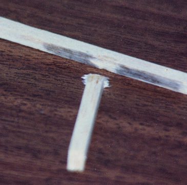
Tension connection Failure - premature failure of a joint usually by pulling the gain off of an adjoining member (see picture below - left).
 .
.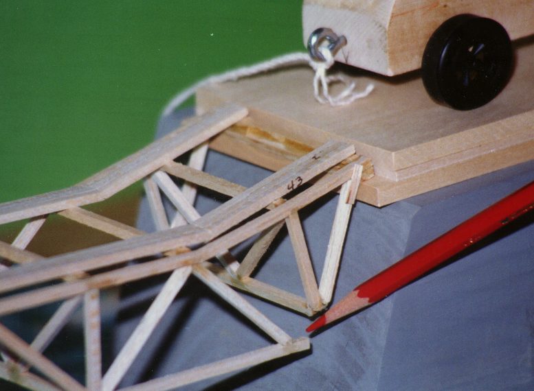
Sometimes it takes careful examination to determine the real cause of failure.
Loss of a connection can cause a redistribution of load that breaks a member away from the actual failure point (the joint - see picture above - right). [ModelSmart3D assumes that the joint does not fail. Use hat buckram or gussets to reinforce tension connections.]
Lateral torsional buckling - bridge flopping over due to inadequate lateral support. The structure needs some resistance to load perpendicular to the main truss. [To help check for lateral stiffness in a bridge, apply a lateral force (2-5% of the force in the main truss) perpendicular to the truss. This will give ModelSmart3D some load to work with. In the case of gravity towers be sure to test the structure's sensitivity to horizontal load.]
Inadequate bracing of a compression member - bracing
a compression member to increase its load carrying capability
and not bracing it in at least two orthogonal directions. That
is, the member ends up buckling in another direction. [ModelSmart3D
allows for user defined effective (buckling) lengths. Please refer
to pages 8-7 and 8-8 of the manual for an example. There is also a
discussion of effective length in the ModelSmart(2d) Extra for Experts chapter
- for the pdf version click
here. and the new ModelSmart3D manual chapter
Extra for Experts ]
]
Local failure - failure at the location where the load is attached.
Failure of the glue - the joint could fail because not enough adhesive is present at the interface between the adjoining members thus causing the glue material to be over stressed and break or stretch so much that it causes a redistributed of load followed by a secondary failure away from the joint.
Wrong supports - Try so select supports that represent how the actual model will deform when the load is applied.
For example, use the classic hinge roller combination for bridge supports. Fixed supports are usually not appropriate because you are not going to glue the bridge to the test apparatus. The roller (x roller - if you are drawing your bridge so that is spans in the x direction) support correctly allows some slippage and rotation to occur as the load is applied. The hinge allows rotation to occur but simulates the frictional resistance that prevents the bridge from slipping totally off of the apparatus bearing surfaces. Of course, you will need 2 hinges and 2 rollers in the case of the usual 3d bridge.
*********************************************************************************************
Do not cut members if the actual geometry does not require it. To describe your structure to ModelSmart3D it is necessary to draw members from joint to joint. Therefore, the member may appear cut on the computer screen. Do not cut members when you actually build your model if you can avoid it. For example, usually the bottom chord of a bridge truss can be continuous, even though, when you draw the bottom chord into the program, you must draw it as individual elements that span from joint to joint.
ModelSmart and ModelSmart3D are trademarks of Pre-Engineering Software Corporation. The Bridge Builder, CountyDam, ModelSmart and ModelSmart3D screens are trademarks of Pre-Engineering Software Corporation. SpaceGuide and the SpaceGuide screen are trademarks of Pre-Engineering Software Corporation. Bridge Builder is a registered trademark of Pre-Engineering Software Corporation. Windows 95, Window 98 & Windows NT are either registered trademarks or trademarks of Microsoft Corporation. Pentium is a registered trademark of Intel Corporation. Celeron is a trademark of Intel Corporation. All documents (including programs, photographs and graphics) at this site are : Copyright 1996-2005, Pre-Engineering Software Corporation. All rights reserved. This work may not be republished in any form.