What is the maximum load my tower can support?
Let’s assume that
you are using ⅛” sticks of 18
psf (type BalsaD2).
Using
ModelSmart3D create a very short
column like the one below:
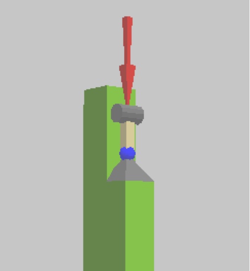
The column above is ½” long. It has a universal hinge at its base. It also has a Y roller at the top so it is free to compress. (I used the “Joints|Size|Small” menu option to make the short column easier to see.) I applied a starting load of -1 lb (one pound in the negative Y direction).
Test the column using
“Analysis|Analysis Options|Find Breaking Force”
menu option set.
I get -35.94 lbs when I test it.
This is the maximum force that this column can
carry.
The reason I used a very short
column is to make sure that the column would
fail in a crushing of the material mode rather
than a buckling mode.
If I increase the length of the
column to 1” long the new max load is still
-35.94 lbs. This means the mode of failure is
still crushing. (Reset the original load back
to 1 lb. before testing again.)
I increased the column length to
2” and tested it again. This time I got -35.14
lbs.
and when I test it at 2.5” long I
get 22.49. These failures indicates a buckling
mode failure.
At 1.9” I get 35.94 lbs; I didn’t buckle.
If you were to build a tower
using the 1/8” BalsaD2 balsa wood and you braced
the columns at no further apart than 1.9” your
tower,
assuming it had 4 legs, should
support about 35.94 times 4 or about 144 pounds
total.
This is an ultimate load there is
no safety factor.
This also assumes your bracing
holds, there are no imperfections in the sticks,
the columns are initially straight and
symetrical, and the cg of the load is placed
exactly in the middle atop your tower.
(As a rule of thumb, your bracing
should be able to support at least 2% of
compressive force in the column placed laterally
at the brace point. In this case, you should
apply a lateral load of about .7 lbs at various
bracing locations to test the sensitivity of
your tower and bracing to lateral load. It
would also be a good idea to assume the test
load is not perfectly placed by placing slight
more load on two of your columns.)
If your tower is x-braced the
diagonal that is in compression may be flagged
as failing but may actually just buckle and bow
out without breaking and remain in place. This
movement can shift the load to the other
diagonal of the x-brace for it to take in
tension. To get the correct maximum
ultimate structure load you can use the
“Member|Negate” menu option to remove the
buckling diagonal from the analysis”.
If you have a slanted leg tower
the maximum ultimate load would be reduced as
follows.
(This is automatically considered
in the ModelSmart3D analysis engine.)
The vertical component of the leg
would be necessarily less than the force
directed along the axis of the skewed column due
to geometrical considerations. Therefore, you
would need to correct the maximum force by the
factor :
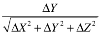
For example, assume the coordinate of the base of your column is (X=0,Y=0,Z=0) and the next joint up along your straight skewed column is (X=.858,Y=5.434,Z=.858) then using the correction factor above:
5.343/sqrt(.858^2+5.434^2+.858^2)
= 5.343/5.568 =
.96
Where deltaX =
.858-0 = .858, deltaY = 5.434-0 = 5.434, & deltaZ = .858-0 =
.858
The max
ultimate capacity ( no safety factor) of your tower would be
(4)(35.94)(.96)
= 138 pounds.